

by Prof. John Atkinson, City University, London
 |
 |
| Back to Compression and shear | Based on part of the GeotechniCAL
reference package by Prof. John Atkinson, City University, London |
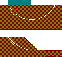 Near any geotechnical
construction (e.g. slopes, excavations, tunnels and foundations) there
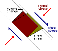
will be both mean and normal stresses and shear stresses. The mean or normal
stresses cause volume change due to compression or consolidation.
The shear stresses prevent collapse and help to support the geotechnical structure. Shear stress may cause volume change.
Failure will occur when the shear stress exceeds the limiting shear stress (strength).
Common cases of shearing | Back to Shear strength |
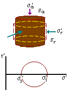
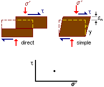
There are simple theories for two special cases.
| 
|
| 
|
It is not possible to draw a Mohr circle for a shear test unless stresses on vertical planes are measured.
Strength | Back to Shear strength |
| Drained direct (ring) shear
| Drained simple shear
|
We explore the relationship between the maximum shear stress and the effective normal stress (s') by ploting a graph of tf against s'.
Some aspects of the behaviour show up more clearly if we normalise the data by plotting tf / s' against s' / s'
Peak strength | Back to Strength |
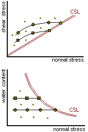 The peak strength is the maximum value of the shear stress or the maximum value of the
ratio of shear stress to effective mean or normal stress. For drained tests these will
occur simultaneously, for undrained tests they may occur at different points and the
definition used here is the maximum stress ratio.
Peak strength in shear tests | Back to Peak strength Forward to Equations |
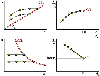
The circle represent the results of a set of shear tests on samples at the same moisture content but different normal stresses. The squares represent the results of a second set of tests at a different moisture content.
We normalise the data by plotting
The basic peak states, before normalisation, fall on different curves each for a particular water content or void ratio.
After normalisation all the peak states fall on a single unique envelope.
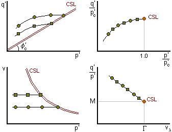 Peak strength in triaxial tests
After normalisation all the peak states fall on a single unique envelope.
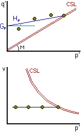 At a given water
content or specific volume all the peak states fall on a single smooth
envelope. This may be represented in one of two ways:
As a power law

As a linear envelope
if the curvature is relatively small over a given range.
q'p = Gp + Hp p'
The parameters a, b and Gp, Hp depend on the water content or voids ratio.
Even at a given water content or voids ratio, the parameters Gp and Hp depend on the range of stress for linear approximation.
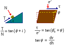 Stresses and displacements
in a shear sample are analagous to the forces and movements of a friction
block on an inclined plane.
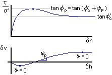 At critical
state
y = 0 and t'
= s' tanf'c
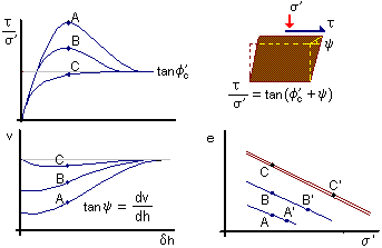
The additional stress ratio (above the critical state) is due to the
rate of dilation
tan y = dv/dh
 At its critical state
soil continues to distort at constant effective stress and at constant
volume.
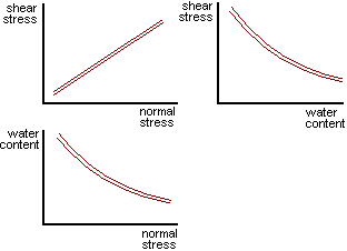
When soil is at its critical state there is a unique relationship between shear stress, effective normal stress and water content (or specific volume or void ratio). Critical states are unique and do not depend on initial state or stress path.
Critical states correspond to shear strains typically 10% to 40%.
Critical shear stress (critical state strength) increases with increasing effective normal stress and with decreasing water content.
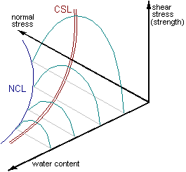
The critical state line can be represented as a graph in 3 dimensions. For isotropic compression, shear stresses are zero and the isotropic normal compression line can also be represented.
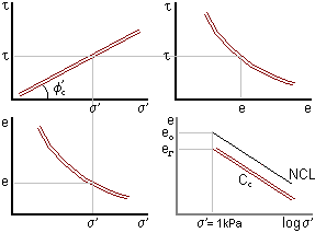
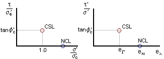
The critical state line can be normalised with respect to the critical pressure s'c or the equivalent void ratio el. The critical state line and the isotropic normal compression line both reduce to single points.
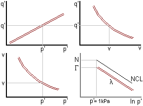
The critical state line can be normalised with respect to the critical
pressure f'c or the equivalent specific
volume vl. The critical state line and the isotropic normal
compression line both reduce to single points.
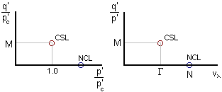
| Typical values | l | G | M | f' |
| high plasticity clay | 0.16 | 2.45 | 0.89 | 23º |
| low plasticity clay | 0.10 | 1.80 | 1.18 | 29º |
| quartz sand | 0.16 | 3.00 | 1.28 | 32º |
| carbonate sand | 0.34 | 4.35 | 1.65 | 40º |
For fine-grained soils the gradient l or
Cc of the critical state line is related to the Atterberg limits
by
Cc = (Ip x Gs) / 200
l = (Ip x Gs) / 460
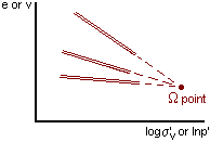 For many soils
the critical state lines all pass through a single point called the W
(omega) point.
v(W) = 1.25 p'(W) = 10MPa
e(W) = 0.25 s'(W)
= 15MPa.
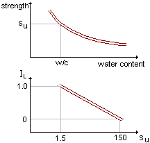 The critical state
strength is uniquely related to the water content.
If the soil is sheared without change of water content (i.e. undrained) its strength remains the same. This is called the undrained strength su. But if the soil is not undrained and the water content changes the strength will also change.
The undrained strength is directly related to the liquidity index IL.
Some authors give slightly different values for su but
su at PL (i.e. IL=0) is always 100 times
su at LL (i.e. IL=1)
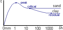 This is the very
lowest strength which occurs after very large displacements. For sands
the residual strength is the same as the critical state strength. For clays
the residual is about ½ the critical state strength. For clays the
flat clay particles become aligned parallel to the direction of shear.
The residual strength occurs after very large (>1m) movements and is not usually relevant for geotechnical engineering where generally ground movements must be small. However, on old landslides there may have already been very large movements and in such cases the strength may already be at the residual before construction starts.
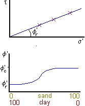 Residual strength
applies to clays after very large shear displacements when clay particles
have become aligned in well-defined shear zones or slip planes.
![]()