Piled foundations
Adapted from the Foundation section of the GeotechniCAL
Reference Manual Author: David Toll (Durham Univ.)
Piles generally used because adequate bearing capacity can not be found
at shallow enough depths to support the structural loads. It is important
to understand that piles get support from both end bearing and skin friction.
The proportion of carrying capacity generated by either end bearing or
skin friction depends on the soil conditions. Piles can be used to support
various different types of structural loads.
Types of piles
- End bearing piles
- Friction piles
- Settlement reducing piles
- Tension piles
- Laterally loaded piles
Pile construction
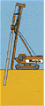
- Displacement piles
soil is displaced radially as well as vertically as the pile shaft
is driven or jacked into the ground
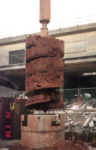
- Non-displacement (or replacement) piles
soil is removed and the resulting hole filled with concrete or a
precast concrete pile is dropped into the hole and grouted in.
Choice of pile Depends on:
- Location and type of structure
- Ground conditions
- Durability
- Cost
Pile groups
- Piles are frequently installed in groups.
- A pile group must be considered as a composite block of piles and soil,
and not a multiple set of single piles.
- The capacity of each pile may be affected by the driving of subsequent piles in close proximity.
- Compaction of the soil between adjacent piles is likely to lead to higher
contact stresses and thus higher shaft capacities for those piles.
- The ultimate capacity of a pile group is not always dependent on the individual
capacity of each pile.
- When analysing the capacity of a pile group 3 modes of failure must be
considered:
- Single pile failure.
- Failure of rows of piles.
- Block failure.
Ultimate Bearing Capacity
The ultimate bearing capacity may be take as one of three values:
- the maximum load Qmax, at which further penetration occurs without
the load increasing
- a calculated value Qf given by the sum of the end-bearing and
shaft resistances
- or the load at which a settlement of 0.1 diameter occurs (when Qmax
is not clear).
For large-diameter piles, settlement can be large, therefore a safety factor
of 2-2.5 is usually used on the working load.
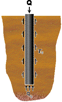
A pile loaded axially will carry the load partly by shear stresses,
ts,
generated along the shaft of the pile and partly by normal stresses, qb,
generated at the base.
The ultimate capacity Qf of a pile is equal
to the base capacity plus the skin friction acting on the shaft.
| Qf = |
Qb |
+ |
Qs |
|
| = |
Ab . qb |
+ |
å (As . ts) |
|
| where |
Ab is the area of the base
As is the surface area of the shaft within a soil layer. |
The proportions of capacity contributed by skin friction and end bearing
do not depend on the geometry of the pile alone. The type of construction
and the sequence of soil layers are important factors.
Settlement
Full shaft capacity is mobilised at much smaller displacements than those
related to full base resistance. This is important when determining the
settlement response of a pile. The same overall bearing capacity may be
achieved with a variety of combinations of pile diameter and length. However,
a long slender pile may be more efficient than a short stubby pile. Longer
piles generate a larger proportion of their full capacity by skin friction
and so their full capacity can be mobilised at much lower settlements.
Driven piles in non-cohesive soil
The base resistance, Qb can be found
from Terzaghi's equation for bearing capacity,
qf = 1.3 c.Nc + qo.Nq
+ 0.4 g.B.Ng
The 0.4g.B.Ng
term may be ignored, since the diameter is considerably less than the depth
of the pile.
The 1.3c.Nc term is zero, since the soil is non-cohesive
(c=0).
The net unit base resistance is therefore qnf = qf
- qo = qo (Nq -1)
and the net total base resistance is Qb = qo
(Nq -1) Ab
The ultimate unit skin friction (shaft) resistance
qs = Ks .s'v
. tand
| where |
s'v |
= average vertical effective stress in a given layer |
|
d |
= angle of wall friction, based on pile material and f´ |
|
Ks |
= earth pressure coefficient |
Qf = Ab qo Nq + S(Ks
.s'v .tand .As)
Calculate Nc, Nq
and Ng
Values of Ks and d can be related
to the angle of internal friction (f´)
using the following table according to Broms.
| Material |
d |
Ks |
|
|
low density |
high density |
| steel |
20° |
0.5 |
1.0 |
| concrete |
¾ f´ |
1.0 |
2.0 |
| timber |
2/3; f´ |
1.5 |
4.0 |
Like much of pile design, this is an empirical relationship.
From empirical methods it is clear that Qs and Qb
both reach peak values at a depth of between 10 and 20 diameters.
It is usually assumed that skin friction never exceeds 110kN/m²
and base resistance will not exceed 11000kN/m².
Driven piles in cohesive soil
Driving piles into clays alters the physical characteristics of the soil.
In soft clays, driving piles results in an increase in pore water
pressure, u, causing a reduction in effective stress. Ground heave
also occurs. As the pore water pressure dissipates with time and the ground
subsides, the effective stress in the soil will increase. The increase
in effective stress (s' = s
- u) leads to an increase in the bearing capacity of the pile with
time. In most cases, 75% of the ultimate bearing capacity is achieved within
30 days of driving.
For piles driven into stiff clays, a little consolidation takes place,
the soil cracks and is heaved up. Lateral vibration of the shaft from each
blow of the hammer forms an enlarged hole, which can then fill with groundwater
or extruded porewater. This, and 'strain softening', which occurs due to
the large strains in the clay as the pile is advanced, lead to a considerable
reduction in skin friction compared with the undrained shear strength,
su,
of the clay. To account for this in design calculations an adhesion factor,
a,
is introduced. Values of a can be found from empirical data previously
recorded. A maximum value (for stiff clays) of 0.45 is recommended.
The undrained shear strength, su,
frequently increases with depth. The value used to calculate the
end bearing capacity, Qb, should be that at the base of the
pile. The value used to calculate the shaft capacity, Qs,
should be the average value, su(avg), take at mid height.
Qs = a .su(avg)
.As
Qb = su .Nc .Ab
Nc = 9.0 for clays and silty clays.
Bored piles in non-cohesive soil
The design process for bored piles in granular soils is essentially the
same as that for driven piles. It must be assumed that boring loosens the
soil and therefore, however dense the soil, the value of the angle of friction
used for calculating Nq values for end bearing and d values
for skin friction must be those assumed for loose soil. However, if rotary
drilling is carried out under a bentonite slurry f' can be taken as that
for the undisturbed soil.
Bored piles in cohesive soil
Following research into bored cast-in-place piles in London clay, calculation
of the ultimate bearing capacity for bored piles can be done the same way
as for driven piles. The adhesion factor should be taken as 0.45. It is
thought that only half the undisturbed shear strength is mobilised by the
pile due to the combined effect of swelling, and hence softening, of the
clay in the walls of the borehole. Softening results from seepage of water
from fissures in the clay and from the unset concrete, and also from 'work
softening' during the boring operation.