Buoyancy-dependent foundations
Lecco bypass, near Milan, ItalyThe Italian road authority ANAS' bypass includes twin bore 3.2km long tunnels passing underneath Monte Barro and approach viaducts of 200m and 950m at either end. At the longer of the two, the underlying limestone bedrock dips in a 100m deep glacial valley, now infilled with soft and loose lake deposits. A brave design concept was proposed, in which hydrostatic upthrust supports the viaduct's load.
While floating roads built on lightweight polystyrene blocks have been constructed over marshland, at Lecco the viaduct is to be built on 20 huge, jet grouted cylindrical cells, bedded 25m below the ground surface. Soil within each cell is excavated from the surface using a backhoe. The cells are lined with concrete and PVC, and a 1m thick cap completes the hollow space.
The foundation design is dependent almost entirely upon buoyancy, provided by the cells being water tight and remaining air filled. Yet water has leaked into some of the completed cells and permanent pumping may be necessary to keep some of the cells dry.
jet grouted cylindrical cells
The cells are formed by vertically drilling a 10m diameter ring of
31 overlapping 1.5m diameter jet grouted columns. Each column is reinforced
by a steel pipe inserted into the soil-grout mix before it sets. A second
outer ring of jet grouting is then constructed over the bottom 13m of the
cell while a third phase of jet grouting forms a consolidated 5m deep plug
between 20m and 25m depth.
A 300mm thick reinforced concrete wall is
cast in place after every 2m of excavation until the top of the plug section
has been reached. The base is then strengthened with a 2.5m thick reinforced
concrete slab and a PVC geomembrane is installed to waterproof the sides
of the cell. Then a second internal concrete wall is cast.
Wellpoint pumping
 Sevenoaks, Kent
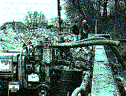
In preparation for the construction of the piling mattress for a new superstore, subcontractors commenced dewatering to lower the water table within the fine silty sands of the Lower Greensand. The Gault clay dips down towards the northern end of the site, making dewatering unnecessary in this area, so the wellpoints were installed along the bank of the stream at the east boundary, and around the southern boundary. Groundwater in that area is almost at surface level.
120 wellpoints were installed, the aim being to dewater the Greensand down to 4m, allowing excavation for the construction of the pile mat. The wellpoints were connected to a pair of six-inch pumps which discharge directly into the stream. Initially, the pumps were discharging at a rate of 40 litre/sec, but after four days this had dropped to 10-15litre/sec. The Gault clay contained a number of perched water tables, and these were sump pumped during the first week of dewatering in order to drain them.
GEOLOGY
The geology consists of a layer of made ground overlying alluvium with
some peat deriving from the time when the area was marshland. This overlies
Gault clay and an extremely fine sand which represents the top of the Lower
Greensand.
Site investigation
Site investigation consisted of eight boreholes and 16 trial pits,
two of which were prevented from going to full depth because of the high
groundwater inflows.
Artificial island
 Trans Tokyo
Bay Highway, Japan
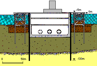
Record breaking diaphragm walls has been trenched 135m under Tokyo bay at the artificial island of Kawasaki - a key feature of the £5000M Trans Tokyo Bay Highway.(Note 1) The island will serve a dual role as the main pit for tunnel driving during construction, and later as a ventilator opening into the highway tunnel.
Loose marine sands have been stabilised by compaction from a barge before construction of the working platforms. Note 2 The support framework functions as part of a retaining wall when fill is placed to form a mounded island to sea level. The wall is supported and protected from erosion by rockfill armour on the outside.
A rig worked from the platform to trench out the 98m diameter, 135m deep ring of diaphragm wall panels, slicing down through the placed fill, then marine material, to form a cut off in hard rock. Once the wall was watertight, the interior was excavated to form a pitNote 3 reaching 70m below sea level. Tunnel drives then started from the dry chamber.
(Note 1)
The Yokohama Bay bridge carries the new road 860m across the water
from Kisarazu. The rest of the distance to a second artificial island is
spanned by a 4.4km low level viaduct. From there the road plunges beneath
the sea carried through twin 9.1km tunnels to the mainland.
(Note 2)
A 200m diameter ring of steel trestle working platforms, founded on
tubular steel piles driven into the treated material.
(Note 3)
Over 0.5M.m³ of fill and soft sediment will have to be dug out
while in situ reinforced concrete supports are erected inside.
Flooded tunnel and ground freeze
Thames Water ring main, LondonMore than twice the depth of London's deepest tube station, the tunnel was being driven for the Streatham to Brixton section of Thames Water's ring main. Groundwater pressures approaching 400kN/m² meant that compressed air fed into the workings to stem the flow broke through the legal limit of 345kN/m² for man working. The 2.5m diameter drive was started in dry London Clay before breaking into the underlying Woolwich & Reading beds. Saturated sand beds up to 0.5m thick needed more than the 100kN/m² air pressures predicted to keep the tunnel dry. Even raising the air to over 200kN/m² did not prevent water ingress.
The miners were probing to see how much Woolwich & Reading bed material protected them from the tricky Thanet Sands below, when the tunnel blew, letting 400kN/m² pressurised groundwater blast in, bringing with it more than 10m³ of sand and exposing the Chalk below. The volumes and rate of tunnel inflow, coupled with the fact that there is no sign of depressurising the Thanet Sands, indicates that the water is coming from the Chalk.
Fortunately, the tunneller was stranded below open ground, so a 50m vertical shaft can be sunk for machine recovery. The base of the 7m diameter shaft will be frozen to allow a short horizontal drive to the machine.
Rising groundwater levels
 The deep aquifer
beneath London
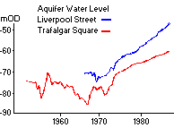
Many major cities obtain water by pumping from the ground. Changed industrial practices and water-supply systems over the years have led to much less water being taken from these sources. As a result, water levels which had been drawn down are now rising.
During the past two centuries, the pumping from the deep aquifer lowered the groundwater level by as much as 70m. The level is now rising, in many areas by about 1m/yr. If the rise continues for 20 to 30 years, the water pressures in the sands and clays above the Chalk will increase, causing ground movements in the clays. This could damage some large buildings and tunnels and increase leakage into them. These problems can be prevented by additional pumping, for a capital expenditure which is small compared with the potential cost of damage.
Deep aquifer
The water-bearing Basal Sands and Chalk below London are referred to
as the deep aquifer. The aquifer is confined over much of the Basin by
the overlying thick, relatively impermeable layers of clay, which separate
the deep aquifer from the perched groundwater in the overlying gravels.
Future water levels
A regional groundwater computer model has been used to estimate the
rates of rise likely to occur over the next 90 years, together with the
likely maximum future groundwater levels. It shows that water levels could
return almost to their original values within the next 30 to
40 years, unless action is taken.
Additional pumping
Additional pumping of water from the aquifer in Central London not
exceeding 30 mega-litres per day would be sufficient. This is about 5%
of the normal daily consumption of water in Central London.
Capital Expenditure
The pumping would require about 30 wells at a capital cost of £10M
to £30M.
Potential cost
The cumulative cost of remedial works for tunnels could exceed £10M.
Repairs to large buildings could cost tens of millions of pounds. Costs
of new construction would also increase.
Effects on buildings and tunnels
 The potential
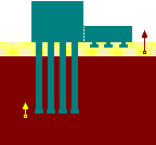
effects of rising groundwater levels on buildings are:
- damage, perhaps instability caused by differential ground movements
- seepage into basements
- chemical attack on buried steel and concrete
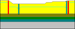
Although older buildings are unlikely to be damaged, modern structural forms, such as those in the diagram, would be vulnerable. If water levels rise causing the clay to swell, the two parts of the building with differing foundation levels will heave by amounts which could differ by up to 100mm.
There are some 130km of tunnels under London which are located near
the base of the London Clay or in the sandy deposits. Lengths totalling
about 40km have been identified which could suffer increased seepage, loading
and chemical attack.
Simulation of rising groundwater
 Canary Warf,
London
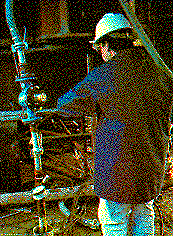
Concern over rising groundwater at Canary Warf has led to the testing of a variable water pressure trial pipe: The piezometric head is being artificially increased in the Thanet sands pile founding strata by injecting water into five 150mm diameter wells. Bourdon gauges connected to three piezometers monitor changes in head during testing. The experiment models the change in pile base effective stress which is predicted if London ground water levels continue to rise, plus the effect of unloading under the 9m deep excavation for Founders Court car park. Trial excavation has been made redundant.
The total change in vertical effective stress at the pile base is equal to the sum of changes in total vertical stress and water pressure. The reduction in vertical effective stress is calculated to be about 180kPa, roughly equivalent to the 17m increase in water head induced by injection into Thanet Sands. This compares with a current vertical effective stress of 300kPa. The potential effect could be very serious if the factor of safety and design were inadequate.
Flooded cofferdam
- Ennerdale Link road, River Hull
The 2.5km dual carriageway road has been designed to relieve traffic congestion in eastern Hull and provide a direct link to the docks. Its planned route beneath the River Hull lies through an overall 361m long retained cutting, including a central 81m twin-celled concrete box section constructed in cut-and-cover through the river bed.
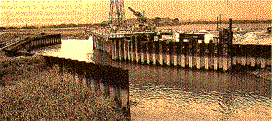
Original site investigation suggested a 4.3m deep layer of alluvium was underlain by a minimum 4m thick bank of impermeable boulder clay. This protected and confined a large aquifer in the chalk beneath it. The aim was to found the tunnel box in the clay zone without affecting the chalk. To construct the tunnel in two halves across the river, the contractor drove the first of two sheetpiled cofferdams on the eastern bank. With the cofferdam dewatered and being bottomed up, a 2m diameter sinkhole suddenly appeared in the river bed close to the cofferdam's north west corner, and a second hole formed nearby inside the structure. The excavation totally flooded overnight.
The cofferdam was quickly plugged with tremmied concrete and following a detailed three month second site investigation, urgent work started on jet grouting down the three exposed faces of the cofferdam, while the possible solutions were debated.
sheetpiled cofferdams
The 140m long, 9m deep cofferdam projected 12m into the diverted river.
The 22m long piles extended down through the boulder clay to found well
into the chalk beneath.
The second investigation
The second investigation revealed the boulder clay to be thinner than
expected. It may contain perched water lenses and a prime concern is its
integrity to protect the aquifer beneath. Water in the cofferdam has come
from the river, not the aquifer, and it is possible that it has leaked
through the sheetpiling rather than migrated beneath it.
Possibel solutions
Protecting the 21m wide tunnel from uplift hydrostatic pressure from
the aquifer would need extensive mass concrete loading to the 1m thick
tunnel floor. Ground anchors to hold the tunnel down are an option, but
could puncture the aquifer.
The tunnel was eventually abandoned in favour of a lift bridge. In excess of £10m has been spent on the aborted work prior to starting on the bridge.
 The Sizewell
B power station
 Rheinberg,
West Germany
 Blackwater
Valley
 Munich airport,
West Germany