
by Prof. David Muir Wood, Bristol University
 |
|
| Back to home page | Based on part of the GeotechniCAL
reference package by Prof. David Muir Wood, Bristol University |
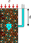 In general, the water in the voids of an element of saturated soil will be under pressure, either due to the physical location of the soil or as a result of external forces. This pressure is the pore water pressure or pore pressure u. It is measured relative to atmospheric pressure.
When
there is no flow, the pore pressure at depth d
below the water surface
is: u = gw d
 The level in the ground at which the pore pressure is zero (equal to atmospheric) is defined as the water table or phreatic surface.
When there is no flow, the water surface will be at exactly the same level in any stand pipe placed in the ground below the water table. This is called a hydrostatic pressure condition.
The pore pressure at depth d below the water table is: : u = gw d
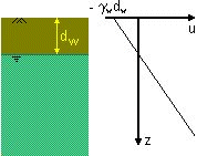 In fine grained soils,
surface tension effects can cause capillary water
to rise above the water table. It is reasonable to assume that the pore pressure varies linearly with depth,
so the pore pressure above the water table will be negative.
If the water table is at depth dw then the pore pressure at the ground surface
is uo = -
gw.dw
and the pore
pressure at depth z is u = gw (z -
dw)
Where the water table is deeper, or where evaporation
is taking place from the surface, saturation with capillary water may not
occur. The height to which the soil remains saturated with negative pore
pressures above the water table is called the capillary rise.
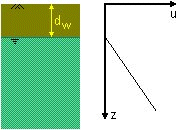 Below the water table the soil can be considered to be saturated.
In coarse-grained soils, water will drain from the pores and air
will therefore be present in the soil between the ground surface and the water table.

Show the graph of water pressure
Click on a soil layer to display a description
The description appears in the status bar when the mouse is held over a layer.
In Internet Explorer is also appears as a popup label
|
Pore pressure at a given point (e.g. point A in the diagram) can be measured by the height of water in a standpipe located at that point. Pore pressures are often indicated in this way on diagrams. The height of the water column is the pressure head (hw)
|
 | |||
To identify significant differences in pore pressure at different
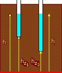
points, we need to eliminate the effect of the points' position. A height
datum is required from which locations are measured. The elevation
head (hz) of a point is its height above the
datum line. The height above the datum of the water level in the standpipe
is the total head (h).
|
 |
|
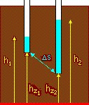
Flow of pore water in soils is driven from positions of higher total head towards positions of lower total head. The level of the datum is arbitrary. It is differences in total head that are important. The hydraulic gradient is the rate of change of total head along the direction of flow. i = Dh / Ds In each diagram there are two points, a small distance Ds apart,
hz1 and hz2 above datum.
|
|
|
In the second diagram, the total heads are different. The hydraulic gradient is i = (h2 - h1) / Ds and the pore water tends to flow. |
 |
 All strength and stress:strain characteristics of soils can be linked to changes in
effective stress
Effective stress (s') = total stress (s) - pore water pressure (u)
s' = s - u
 Darcy's law
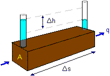
The rate of flow of water q (volume/time) through cross-sectional area A is found to be proportional to
hydraulic gradient i according to Darcy's law:
| v = | q | = k.i i = | Dh |
|---|---|---|---|
| A | Ds |
The coefficient of permeability of a soil is a measure of the conductance (i.e. the reciprocal of the resistance) that it provides to the flow of water through its pores.
The value of the coefficient of permeability k depends on the average size of the pores and is related to the distribution of particle sizes, particle shape and soil structure. The ratio of permeabilities of typical sands/gravels to those of typical clays is of the order of 106. A small proportion of fine material in a coarse-grained soil can lead to a significant reduction in permeability.
Permeability of all soils is strongly influenced by the density of packing of the soil particles
which can be simply desrcibed through void ratio e or porosity n.
Sands
For filter sands it is found that k » 0.01 (d10)˛ m/s where d10
is the effective particle size in mm. This relationship was proposed by Hazen.
The Kozeny-Carman equation suggests that, for laminar flow in saturated soils:

where ko and kT are factors depending on the shape and tortuosity of the pores respectively, Ss is the surface area of the solid particles per unit volume of solid material, and
gw and h are unit weight and viscosity of the pore water. The equation can be written simply as

Clays
The Kozeny-Carman equation does not work well for silts and clays. For clays it is typically found that

where Ck is
the permeability change index and ek is a reference void ratio.
For many natural clays Ck is approximately equal to half the natural void ratio.
 Consider a stratified soil having horizontal layers of thickness
t1, t2, t3, etc. with coefficients of permeability k1,
k2 k3, etc.
For vertical flow, the flow rate q through area A of each layer is the same.
Hence the head drop across a series of layers is

The average coefficient of permeability is

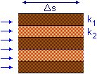 For horizontal flow, the head drop
Dh over the same flow path length
Ds will be the same for each layer.
So i1 = i2 = i3 etc. The flow rate through a layered block of soil of
breadth B is therefore

The average coefficient of permeability is

Darcy's Law relates flow velocity (v) to hydraulic gradient (i).
The volume flow rate q is calculated as the product of flow velocity v and total cross sectional area:
q = v.A
At the particulate level the water follows a tortuous path through the pores.
The average velocity at which the water flows through the pores is the ratio of volume flow rate
to the average area of voids Av on a cross section normal to the macroscopic direction of flow.
This is the seepage velocity vs

Porosity of soil is related to the volume fraction of voids


Seepage velocity can be measured in laboratory models by injecting dye into the seeping pore water
and timing its progress through the soil.
The flow of water through confined spaces is controlled by its viscosity h and the
viscosity is controlled by temperature.
An alternative permeability K (dimensions: length˛ ) is sometimes used as a more absolute coefficient depending
only on the characteristics of the soil skeleton.

The values of k at 0°C and 10°C are 56% and 77% respectively of the value measured at 20°C.
In steady-state flow, the pressures and flow rates remain constant over time.
In transient flow, the pressures and flow rates are time-dependent.
Steady one-dimensional flow is the simplest case, to which Darcy's law can be applied.
This can be extended to cases of variable aquifer thickness and radial flow.
The analysis of steady two-dimensional flow is more complex and results in flow nets.
| Steady downward flow occurs when water is pumped from an underground aquifer. Pore pressures are then lower than hydrostatic pressures. | 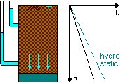
|
| Steady upward flow occurs as a result of artesian pressure when a less permeable layer is underlain
by a permeable layer which is connected through the ground to a water source providing pressures higher
than local hydrostatic pressures.
The fountains of London were originally driven by artesian pressure in the aquifers trapped beneath the London clay. Pumping from aquifers over the centuries has lowered the water pressures below artesian levels. |  |
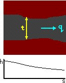 Where flow occurs in a confined aquifer whose thickness varies gently
with position the flow can be treated as being essentially one-dimensional.
The horizontal flow rate q is constant. For an aquifer of width B and varying thickness t, the discharge velocity

and Darcy's Law indicates that

Hydraulic gradient varies inversely with aquifer thickness.
 Steady-state pumping to a well which extends the full thickness of a
confined aquifer
is a one-dimensional problem which can be analysed in cylindrical coordinates: pore pressure or head varies
only with radius r.
Darcy's Law still
applies, with hydraulic gradient dh/dr and area A varying with radius: A =
2pr.t


where ro is the radius of the borehole and h0 the constant head in the borehole.
Pumping from a borehole can be used for deliberate groundwater lowering in order to facilitate excavation.
This is an example of quasi-one-dimensional radial flow with flow thickness t=h.
Then A=2pr.h and


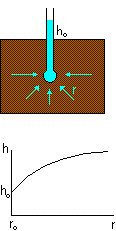 Variation of pore pressure around a point source or side (for example,
a piezometer being used for in-situ determination of permeability) is a one-dimensional problem which can be
analysed in spherical coordinates: pore pressure or head varies only with radius r.
Darcy's Law still applies, with hydraulic gradient dh/dr and area A varying with radius:
A=4pr˛


where r0 is the radius of the piezometer and h0 the constant head in the piezometer.
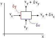 Two-dimensional steady flow of the incompressible pore fluid is governed by Laplace's equation
which indicates simply that any imbalance in flows into and out of an element in the x direction
must be compensated by a corresponding opposite imbalance in the y direction. Laplace's equation
can be solved graphically, analytically, numerically, or analogically.
For a rectangular element with dimensions dx,
dy and unit thickness, in the x direction the velocity of flow
into the element is

the negative sign being required because flow occurs down the hydraulic gradient.
The velocity of flow out of the element is

Similar expressions can be written for the y direction. Balance of flow requires that

and this is Laplace's equation. In three dimensions, Laplace's equation becomes

For a soil with permeability kx and ky in the x and y directions respectively, Laplace's
equation for two-dimensional seepage becomes

This can be solved by applying a
scale factor to the x dimensions so that transformed coordinates xt are used

In the transformed coordinates the equation regains its simple form

and flownet generation can proceed as usual. Calculations of flow are made using an equivalent permeability

It may be preferable in some cases to transform the y coordinates using:

The equivalent permeability remains unchanged.
For many natural sedimentary soils seasonal variations in the depositional regime have resulted in horizontal
macroscopic permeabilities significantly greater than vertical permeabilities. Transformation of coordinates
lends itself to analysis of seepage in such situations.
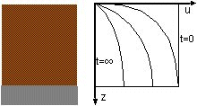 Since water may be regarded as being essentially incompressible,
unsteady flow may arise when water is drawn into or expelled from pores as a result of changes in the size of pores.
This can only occur as a result of changes volume associated with changes in effective stress.
The time-dependent transient change in pore pressure that occurs as a result of some perturbation,
and associated change in effective stress is called consolidation.
One-dimensional compression tests in an oedometer define the relationship between vertical effective stress
s'v and specific
volume v or void ratio e from which a one-dimensional compliance mv can be defined

Then, under conditions of constant total stress, consolidation is governed by a diffusion equation:


where cv is the coefficient of consolidation having dimensions (length˛/time).
Solutions of the consolidation equation are typically presented as isochrones, i.e. variations of pore pressure
with position at successive times, but can also be converted to curves linking settlement with time.
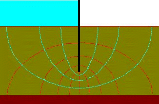 Solutions to Laplace's equation for two-dimensional seepage can be
presented as flow nets.
Two orthogonal sets of curves form a flow net:
equipotentials connecting points of equal total head h
flow lines indicating the direction of seepage down a hydraulic gradient
If standpipe piezometers were inserted into the ground with their tips on a single equipotential
then the water would rise to the same level in each standpipe.
(The pore pressures would be different because of their different elevations.)
There can be no flow along an equipotential, because there is no hydraulic gradient,
so there can be no component of flow across a flow line. The flow lines define channels
along which the volume flow rate is constant.
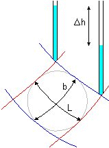 Consider an element from a flow channel of length L between equipotentials
which indicate a fall in total head Dh and between flow lines b apart.
The average hydraulic gradient is

and for unit width of flow net the volume flow rate is

There is an advantage in displaying or sketching flownets in the form of curvilinear 'squares' so that a circle
can be insrcibed within each four-sided figure bounded by two equipotentials and two flow lines. Then b = L and
q = kDh
so the flow rate through the flow channel is the permeability multiplied by the uniform interval
Dh between equipotentials.
 For a complete problem, the flownet has been drawn with the
overall head drop h divided into Nd equal intervals:
Dh = h / Nd
with Nf flow channels.
Then the total flow rate per unit width is

It is usually convenient in
sketching flownets to make Nd an integer. The number of flow
channels Nf will then generally not be an integer.
In the example shown, of flow under a sheet pile wall
Nd
;= 10, Nf = 3.5 and q = 0.35kh per unit width.
 Flow across a boundary between two layers of soil
of different permeability produces a refraction effect.
Consideration of continuity of flow and of continuity of velocity normal to the interface shows that

It is not possible to construct a flow net with curvilinear squares on both sides of the interface
unless the head drop between equipotentials is changed in inverse proportion to the permeability ratio.
If the ratio of permeabilities is greater than about 10, e.g. at the boundary of a drainage
layer then construction of the part of the flow net in the more permeable soil is unlikely to be necessary.
 A surface on which the total head is fixed (for example, from the
level of a river, pool, reservoir) is an
equipotential.
A surface across which there is no flow (for example, an impermeable soil layer or an impermeable wall) is a
flow line
For the situation shown, with flow occurring under a sheet pile wall, the axis of symmetry must also be an equipotential.
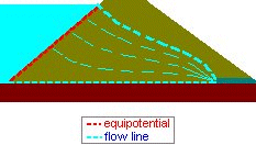 Seepage through an embankment dam is an example of unconfined flow
bounded at the upper surface by a phreatic surface which represents the top flow line and on which the pore pressure
is everywhere zero (atmospheric). Seepage through an embankment dam is an example of unconfined flow
bounded at the upper surface by a phreatic surface which represents the top flow line and on which the pore pressure
is everywhere zero (atmospheric).
|
 Total head changes and elevation changes thus match and for equal head intervals Dh between equipotentials there must be equal
vertical intervals between the points of intersection of equipotentials
with the phreatic surface.
 |
If the flow is upward then the water pressure tends to lift the soil element. If the upward water pressure is high enough the effective stresses in the soil disappear, no frictional strength can be mobilised and the soil behaves as a fluid. This is the quick or quicksand condition and is associated with piping instabilities around excavations and with liquefaction events in or following earthquakes.
 The viscous drag of water flowing through a soil imposes a seepage force on the soil in the direction of flow.
Consider the actual distribution of pore water pressure around an element length L and thickness b taken from a flownet, bounded by two equipotentials with fall in head Dh, and two flow lines.
These pore water pressures are partly supporting the weight gwbL of water in the element and partly providing the seepage force. It is found that the seepage force is
J =
i gw b L
equivalent to a seepage pressure (force per unit volume) in the direction of flow
j = i gw
The quick condition occurs at a critical upward hydraulic gradient ic,
when the seepage force just balances the buoyant weight of an element of soil.
(Shear stresses on the sides of the element are neglected.)


The critical hydraulic gradient is typically around 1.0 for many soils.
Fluidised beds in chemical engineering systems rely on deliberate generation of quick conditions
to ensure that the chemical process can occur most efficiently.
Based on part of the GeotechniCAL
reference package
by Prof. David
Muir Wood, University of Bristol