32 Frederick Street
5 Construction - Rear Elevation
Introduction
The rear elevation is slightly unusual in that there is a single storey, full width extension, probably built in the 1970s. Originally the house probably had a small lean-to extension at the back of the house containing a WC. It is unlikely that the house would have been built with a separate bathroom - there was a probably a tin bath (filled and emptied by hand) in the scullery (now the kitchen).
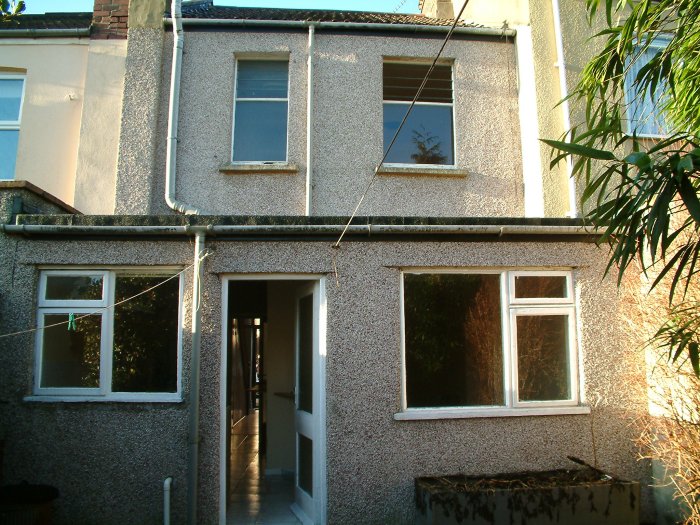 |
The main house wall is 1 brick thick, probably in English Garden Wall bond. When the render is removed from these properties it's sometimes astonishing how few headers there are binding the wall together. The original render was probably as mix of lime and sand, maybe with the addition of some cement or maybe using a hydraulic lime (both designed to give a faster and harder set). The pebble-dash render dates from the 1970s and comprises a surface dressing of stone chippings (the spar or 'dry-dash') thrown onto a sand/cement top coat. A sand/cement render coat lies below the top coat. |
 |
 |
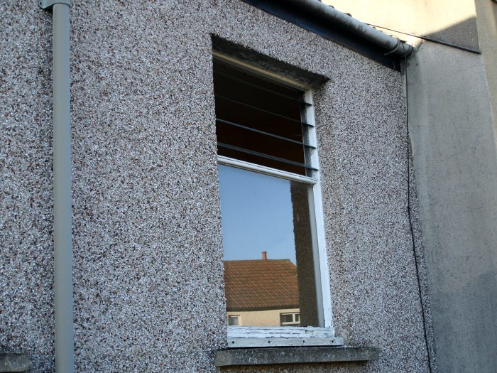
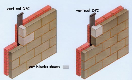
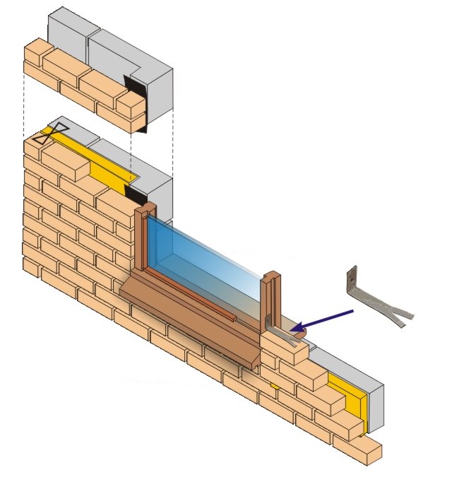
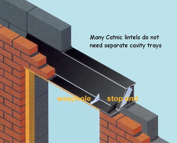
The rear extension is probably cavity construction and is most likely to comprise two 100mm leaves of blockwork with a 50mm cavity. The external leaf is probably dense concrete; the internal leaf may be the same but could be some form of lightweight block. In the 1970s the maximum 'U' value for external walls was quite high - 1.70W/m2K). The 2005 figure was about 0.35W/m2K (the actual value can vary depending on the values of other elements). To form the openings it was normal practice to close the cavity at the jambs by returning the internal leaf to the outside one. The graphic shows typical construction in a brick and block cavity wall. The construction for block and block was no different. The window frame was built in as work proceeded - probably using fixing cramps as shown in the graphic. There's probably a steel, or steel and concrete, lintel at the head. It's unlikely that the cavity is closed at the sill. |
 |
 |
When building extensions like this it is often difficult to know how
best to connect the new structure to the existing one. It use to be accepted
practice to remove some of the bricks in the main wall and 'tooth-in' the
new work to provide a rigid connection. Unfortunately, any minor
differential foundation movement (almost inevitable) would result in
cracking. In modern construction it is more likely to provide a connection
which provides a small degree of flexibility. The wall starter system on the
left (no larger image I'm afraid) is made by Ancon. I presume that the logo
means it's NHBC approved. A similar, and not unrelated, problem is the foundation depth of the new work. What if the existing house has very shallow foundations - should the new extension be at the same depth? There is no easy answer. |
 |
 |
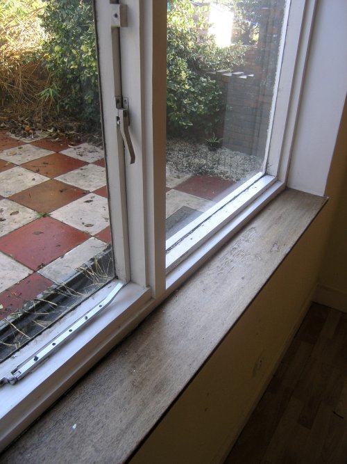
The left-hand image shows the back door. Doors like this don't offer
much protection against forced entry but they were pretty much the standard
type of back door throughout the last 50 years of the 20th century. There
are two other interesting things about this door; firstly the glass is a
safety hazard and secondly, the door frame is not a frame at all - it's
actually a door lining with a planted stop (in the form of a piece of
architrave).
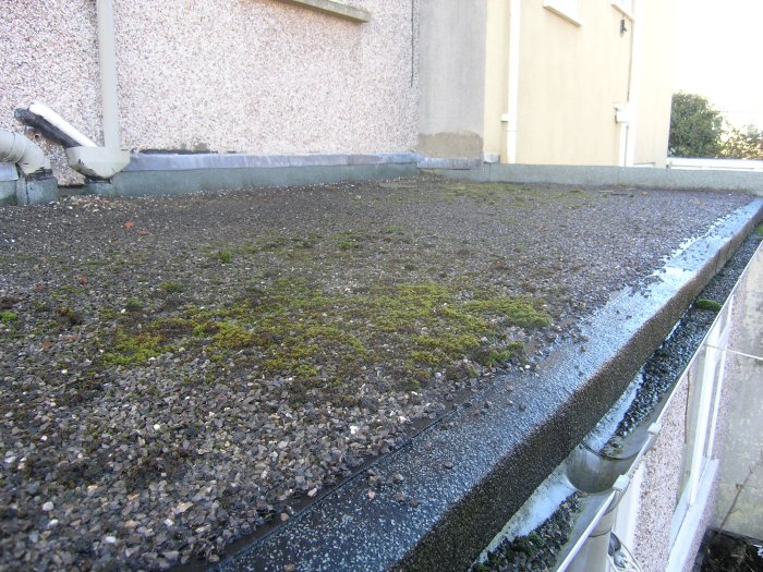
The right-hand image shows the flat roof. This is likely to be a cold roof, probably with 100mm or so of insulation between the joists. The deck may be plywood but it could be chipboard. the ceiling is probably 10mm or 12.5mm plasterboard nailed to the joists. It's doubtful whether there is a vapour check. It was not clear from our brief inspection how this roof is ventilated. |
 |
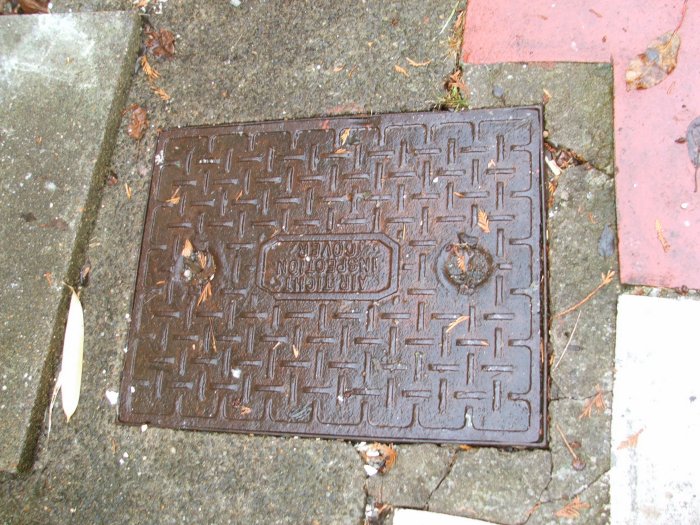 |
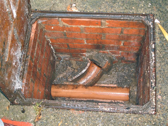
The drainage is not really part of the rear elevation but the inspection chamber cover is right outside the back door. This chamber was probably built at the same time as the extension - we do not know whether there was an inspection chamber on the site originally. The chamber comprises half-brick walls with a cast-iron cover. The builders never got round to completing the chamber - there's no benching. The chamber contains a central, open channel with a 'three-quarter' bend picking up a branch pipe. The cover is of a type often favoured by young marble enthusiasts. |
 |
except where acknowledged